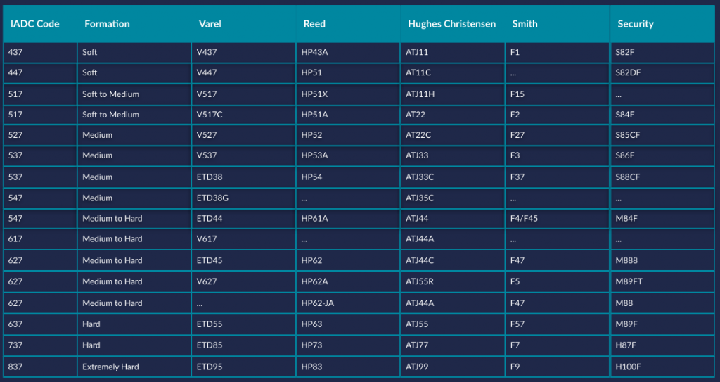
Archives: UiKit2 Modals

Drilling Considerations

Drilling Considerations

The performance and life of the motor is determined by the environment in which it operates. To ensure optimum performance and longest life avoid:

  • Abrasive solids in the circulation system. The drilling fluid should have the least possible sand content (1% or less is recommended).
  • Excessive rotation of motor set with higher bend (Anything over 1.5 degrees is considered high bend).
  • Exceeding recommended weight on bit (WOB) loads.
  • Exceeding the recommended pressure drop across the bit & motor.
  • Repeated stalling of the motor.
  • Tripping without actuation of pumps.

Differential Pressure

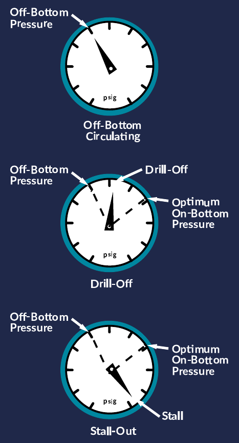
The primary rig reference for HTI motor operation is the rig pressure gauge. Weight (push) indicator can also be used as a drilling reference, however it may give inaccurate information about the actual WOB because of other factors such as the size of the hole the pipe is in, softness of the formation or restrictions reducing the actual WOB. The only true indication of the motor performance is the pressure gauge.

When the motor is off-bottom circulating the pressure gauge shows the total amount of pressure required to pump a known volume of fluid through the motor and bit. This is called the off-bottom pressure.

WOB (placing weight on the bit) creates a higher total pressure. The difference between the off-bottom pressure and the pressure when weight is applied to the bit is called the pressure differential.

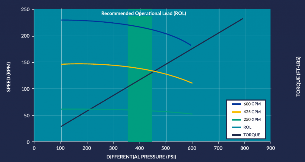
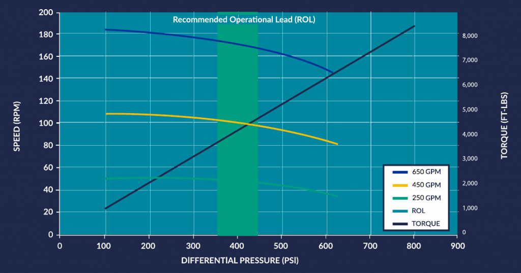
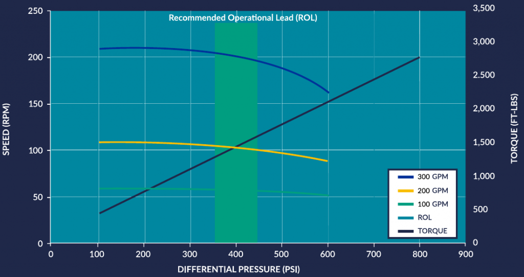
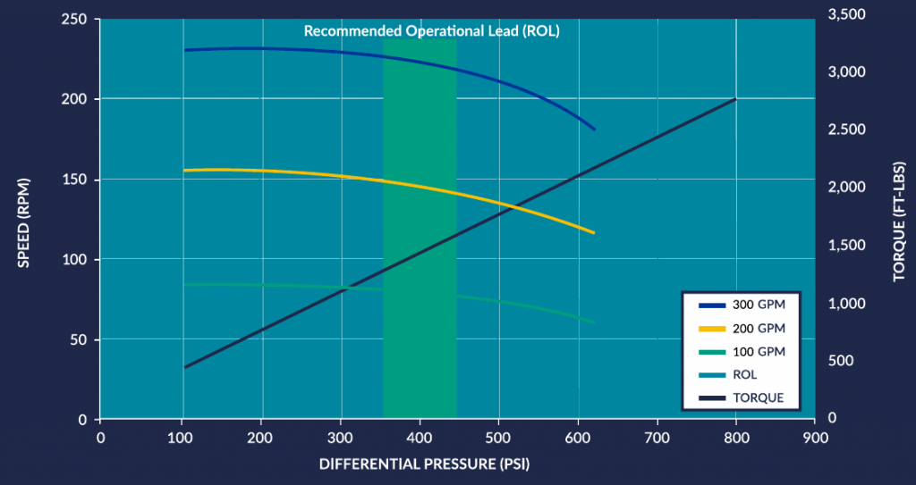
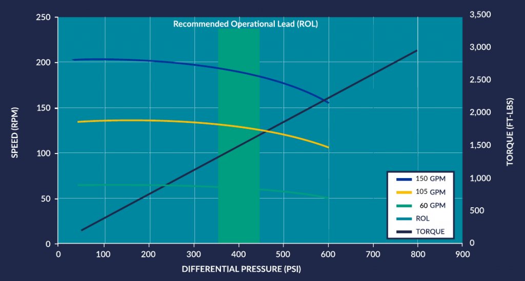
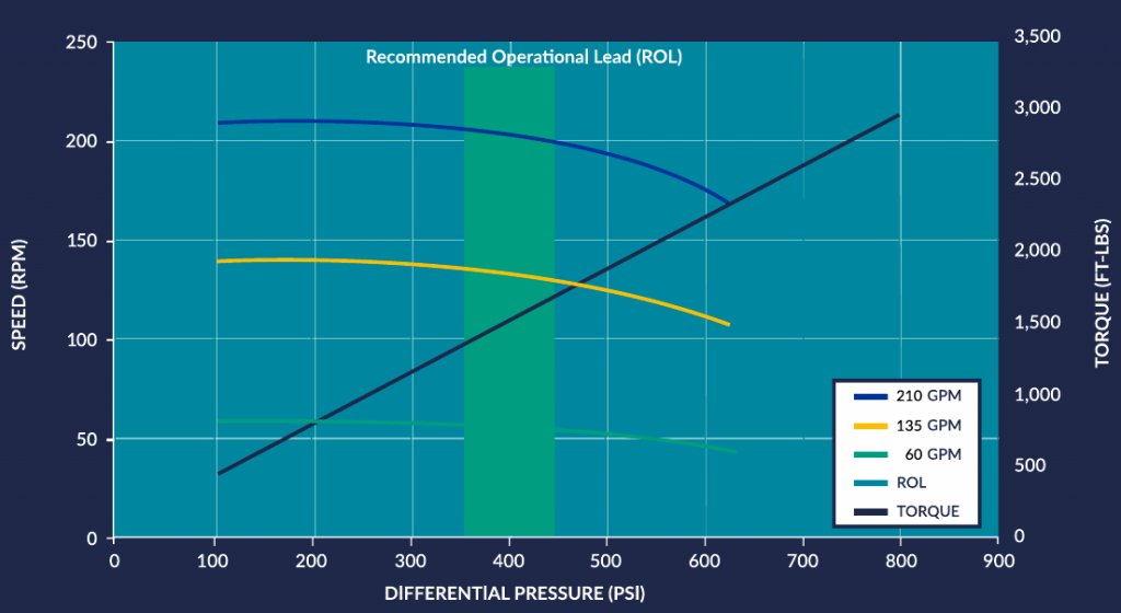
Operate the motor at the recommended differential (the PSI difference between off-bottom pressure and on-bottom pressure. As weight is applied to the bit the pressure will increase. As the bit advances the pressure will decrease until more push (weight) is applied. For best performance and penetration rates maintain optimum on-bottom pressure.

When too much weight or push is applied, exceeding the maximum differential pressure, the motor will stall. The bit will cease to rotate causing the pressure gauge to rise abruptly. Stall pressure is about twice the recommended optimum differential pressure. When a stall happens, stop the pumps and reduce the WOB allowing the pressure to decrease to recommended operational pressures. Do not pull the motor off bottom until normal pressure is resumed. Continual stalling and operating motors in stalled condition can seriously damage the motor. Stalling can lead to tearing or “chunking” of the stator elastomer. When a stator is chunked, motor performance will dramatically decrease or the motor will possibly cease to function.

Filed under: Uncategorized

Adjust Housing Instructions

Adjusting the ABH (if equipped)

Setting the adjustable bend housing is a fairly simple operation.

Below is the procedure for setting the HTI adjustable bend housing:

  1. Tong in the areas as shown in Figure 9. Do not tong on the Orientation Sleeve.
  2. Break apart the ABH connection.
  3. Unthread the Lower ABH Housing two to four complete turns.
  4. Referencing Figure 10 , slide the Orientation Sleeve down to disengage the interlocking teeth.
  5. To adjust the bend angle, rotate the Orientation Sleeve (no more than 1⁄2 turn either direction) unBl the desired bend angle mark is in-line with the identical bend angle mark on the Upper ABH Housing.
  6. Referencing Figure 11, slide the Orientation Sleeve upward so that the interlocking teeth are fully engaged.
  7. Check to see if the desired bend angle marks on both the Upper ABH Housing and the Orientation Sleeve are in-line.
  8. Apply thread dope to the bottom face of the Orientation Sleeve.
    Caution – Do not use thread locking compound on the ABH connections.
  9. While keeping the Orientation Sleeve fully engaged in the Upper ABH Housing, thread on the Lower ABH Housing until it shoulders against the Orientation Sleeve.
  10. Tong in the areas as shown in Figure 9 (above right) and apply the appropriate torque to the connection. See the Table on the next page for the recommended ABH torque values.
  11. The bend angle marks on the Upper ABH Housing and the Orientations Sleeve that match and are in-line with each other until the angle of the ABH. In addition, these matching and in-line bend angle marks indicate the high side of the tool.
Filed under: Uncategorized

8” Motor Specs

Downhole Drilling Motor
800 – 910 – 4.0

  • 8-0” OD
  • 9:10 Lobe
  • 4.0 Stage
  • Slow Speed
  • High Torque

8″ Mud Motor 9/10 Lobe 2 Stage
Slick Bearing Housing

Performance Curve 800-910-4

8-0” Slow Speed / High Torque

Performance Curve 800-910-4-HR

8-0” Slow Speed / High Torque / HR

Filed under: Uncategorized

6 – 3/4” Motor Specs

Downhole Drilling Motor
675 – 910 – 2.0

  • 6-3/4” OD
  • 9:10 Lobe
  • 2.0 Stage
  • Slow Speed
  • High Torque

6 3/4″ Mud Motor 9/10 Lobe 2 Stage
Slick Bearing Housing

Performance Curve 675-910-2

6-3/4” Slow Speed / High Torque

Performance Curve 675-910-2-HR

6-3/4” Slow Speed / High Torque / HR

Filed under: Uncategorized

4 – 3/4” Motor Specs

Downhole Drilling Motor
475 – 910 – 4.0

  • 4-3/4” OD
  • 9:10 Lobe
  • 4.0 Stage
  • Slow Speed
  • High Torque

4 3/4″ Mud Motor 9/10 Lobe 2 Stage
Slick Bearing Housing

Performance Curve 475-910-2

4-3/4” Slow Speed / Medium Torque

Performance Curve 475-910-2-HR

4-3/4” Slow Speed / Medium Torque / HR

Filed under: Uncategorized

3 – 3/4” Motor Specs

Downhole Drilling Motor
375 – 910 – 4.0

  • 4.0 Stage
  • Slow Speed

3 3/4″ Mud Motor 9/10 Lobe 2 Stage
Slick Bearing Housing

Performance Curve 375-910-4

3-3/4” Slow Speed / High Torque

Performance Curve 375-910-4-HR

3-3/4” Slow Speed / High Torque / HR

Filed under: Uncategorized

Jumbo

Jumbo

Dimensions

Suggested RMP

Filed under: Uncategorized